CABIN TEMPERATURE CONTROL
Ata: 21
Sub-Ata: 21-61-05
AIR CONDITION
Location (IPC 21-61-00)
Item: 10
Part Number: 548376-6
Station: 304.5
Zone: 205
Rack: E1-1
Description (AMM 21-61-00)
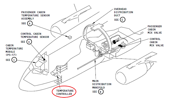
A- Control and passenger cabin automatic temperature regulation is obtained from a single unit located in the electronic compartment. This unit contains all parts of each regulation system which are not required to be mounted remotely. Separate identical networks are enclosed for each cabin.
(1) A built-in test circuit in the temperature controller provides a quick electrical check of temperature control system components. A rotary test switch, two sets of GO, NO GO lights and a test instruction decal are provided on the face of the controller. When the temperature control system is not being tested the switch must be returned to START position.
B- Each network contains a separate power supply, the fixed resistance legs of three different bridge circuits, a control amplifier, a silicon-controlled rectifier actuator control, and a pulse-forming network.
C- The three bridge circuits in use for automatic control are: cabin temperature control bridge, temperature control damping bridge, and duct temperature limit bridge.
D- Each cabin temperature control bridge utilizes two legs which contain variable resistances outside of the controller. One resistance is located in the temperature selector and is manually set to establish the desired temperature reference. The other is a temperature sensor located in the cabin whose resistance varies according to cabin temperature. The bridge is balanced when cabin temperature causes the temperature sensor resistance to equal the selector resistance.
E- The temperature control damping bridge also has the variable resistors of two of its legs remotely located. The resistors are contained in a single duct anticipator sensor in the main distribution manifold. One resistor is thermally impeded by insulation so that it reacts slowly to temperature change. The other is not insulated, and reacts repidly to temperature changes. As a result of a sudden temperature change the resistors will not vary at the same rate and the bridge will become unbalanced.
The damping bridge slows down system response to prevent delivery of excessively hot or cold air to the cabin. It also assists to prevent overshooting and hunting of the temperature control system when a new temperature is selected.
F- The duct temperature limit bridge has only one of its resistances remotely located. The duct limit temperature sensor is located such that it senses the temperature of the conditioned air. As the temperature of the air rises the resistance changes and the bridge becomes unbalanced. If the duct temperature approaches an unsafe level, the temperature limit bridge signal will cancel out heat demand signals of the control bridge.
A polarizing diode between the duct temperature limit bridge and the amplifier prevents the temperature limit bridge having any effect on the control bridge signals during a cooling demand.
G- Each of the three bridge circuits is connected to an amplifier. The amplifier interprets the signals received, and then signals the silicon-controlled rectifier actuator control to shut off current to the mix valve, complete a circuit to move the valve toward cold, or to complete a circuit to move it toward hot.